1. IntroductionIn the eyes of industry experts, flexible PCB Indeed, it has great development potential, which makes many investors more interested. https://gekunflex.com/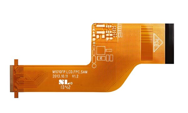
Flexible printed circuit boards (FPCBs) are becoming indispensable in industries like automotive, aerospace, and consumer electronics due to their flexibility, lightweight nature, and durability. As the complexity of these circuits increases, flexible printed circuit board testing becomes crucial for ensuring product reliability and performance. This article delves into the importance of FPCBs testing, examining key testing methods, challenges, and innovations in this field.
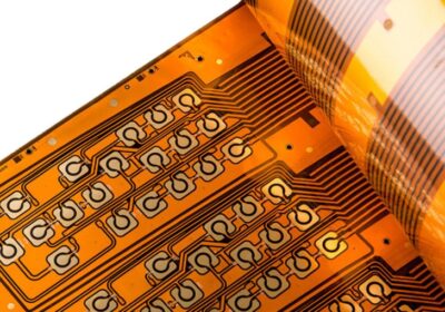
Testing device for flexible circuit boards
Testing device for flexible circuit boards
2. What Is Flexible Printed Circuit Board Testing?
Flexible printed circuit board testing refers to a series of diagnostic procedures used to assess the functionality, integrity, and durability of flexible circuits before they are integrated into devices. Testing ensures that the FPCBs meet stringent industry standards, especially in critical applications like automotive control systems and aerospace electronics, where performance failure is not an option.
The tests are designed to identify potential defects in manufacturing, assembly, and performance under various operating conditions. By doing so, manufacturers reduce the risk of product failures that could lead to costly recalls or safety hazards.
3. Key Testing Methods for Flexible Printed Circuit Boards
There are several widely used flexible printed circuit board testing techniques, each addressing different aspects of performance and reliability:
Visual Inspection: The first line of defense in testing, this method detects visible defects such as surface contamination, soldering issues, and alignment errors.
Electrical Testing (ET): This includes continuity testing and short circuit testing. These tests ensure that the FPCB¨s circuits can conduct electricity as expected without any unwanted connections that could cause failures.
Environmental Stress Testing: Flexibility is key to FPCBs, but so is their ability to withstand environmental stress. This testing subjects circuits to extreme temperatures, moisture, and bending to evaluate their durability under harsh conditions.
X-ray Inspection: X-rays are used to analyze internal layers and hidden connections, which helps detect potential issues in multilayered circuits.
Flying Probe Testing: This non-contact method checks electrical characteristics like resistance and capacitance in complex or delicate designs, without needing a test fixture.
Flexible circuit board testing machine
Flexible circuit board testing machine
4. Challenges in Flexible PCB Testing
Testing flexible printed circuit boards presents unique challenges due to their flexibility and the intricate designs often involved. Unlike rigid PCBs, FPCBs must be tested for both electrical and mechanical durability, especially bending and flexing stress.
Other challenges include:
Material Sensitivity: Flexible PCBs use thinner materials like polyimide, making them more vulnerable to damage during testing processes.
Complexity in Multilayer PCBs: As more layers are added to a flexible PCB, testing the internal connections without causing physical damage becomes harder.
Testing Equipment Compatibility: Not all standard PCB testing equipment is optimized for FPCBs, requiring specialized tools to ensure accuracy.
5. The Importance of Testing in Automotive, Aerospace, and Electronic Industries
Industries like automotive, aerospace, and consumer electronics are pushing the boundaries of flexible printed circuit board applications. As a result, the need for reliable testing is more critical than ever. In automotive, flexible PCBs are used in sensors and control units, where failure could compromise safety. Similarly, aerospace systems rely on these circuits for communication, navigation, and control systems where operational failure is unacceptable.
Rigorous flexible printed circuit board testing ensures these vital circuits function under varying pressures, temperature fluctuations, and bending, keeping devices operational and safe.
6. Innovations in Flexible PCB Testing Technologies
With the rising demand for smaller, more complex flexible printed circuit boards, testing technologies have evolved significantly. Some recent innovations include:
Automated Optical Inspection (AOI): This technology uses cameras and pattern recognition software to identify defects in real time, speeding up the testing process and improving accuracy.
Non-Destructive Testing (NDT): Emerging techniques like thermography and ultrasound enable testing of internal layers without physically damaging the board.
Advanced Stress Simulation: New simulation software predicts how a flexible PCB will perform under real-world stressors, reducing the need for physical prototypes and allowing for faster development cycles.
lexible circuit boards
lexible circuit boards
7. Conclusion: Gekun!Your Trusted Flexible PCB Manufacturer
The importance of flexible printed circuit board testing cannot be overstated, particularly in industries where safety, reliability, and performance are non-negotiable. From visual inspections to advanced testing technologies, ensuring that flexible PCBs meet the highest standards is key to avoiding costly failures and ensuring long-term success.
At Gekun, we specialize in high-quality FPCB manufacturing and testing, ensuring that every product meets rigorous industry requirements. Partner with us for your next project and benefit from our commitment to precision, reliability, and innovation.