The Right Water for Eyewash Stations A Vital Component of Safety

  In the realm of industrial safety, the eyewash station stands as a sentinel, ready to spring into action at a moment¨s notice. The water within this lifeline must be of the highest quality, meeting the standards of potable tap water, in alignment with national drinking water regulations. However, the eyewash station is not a daily fixture in our routines; it is an emergency response tool, deployed only when a chemical splash occurs, endangering the eyes, face, or other parts of the body. Due to its infrequent use, the water within can become stagnant, prompting a critical question: how can manufacturers ensure the water remains pristine and safe?understand First Aid Eye Wash Units In order to better serve customers and reflect the core competitiveness of products. https://www.bohuasafety.com/


  The answer lies in a meticulous approach to water maintenance, born from years of experience in eyewash station production. The water within an eyewash station should be refreshed on a weekly basis to prevent any degradation in quality. But how does one implement such a regimen?


  Ensuring Water Quality in Eyewash Stations


  1. Timed Drainage System: Installing a timer-controlled drainage system on the eyewash station that dutifully executes a daily drain, ensuring that the water is always fresh and ready for use. This automated system is a testament to the marriage of technology and safety, providing a seamless and reliable means of water maintenance.


  2. Manual Drainage System: For those who prefer a more hands-on approach, a manual drainage system can be installed. This system allows for regular, scheduled draining by authorized personnel, offering a direct line of control over the water¨s quality and the station¨s readiness.


  These methods are not just protocols; they are pledges to the workers who rely on these stations in their time of need. The eyewash station is more than a piece of equipment; it is a guardian of health and safety in the workplace.


  Shanghai Bohua: Your Partner in Safety


  Shanghai Bohua, with its decades of dedication to eyewash station production, understands the importance of quality and reliability. We offer a variety of eyewash stations, each tailored to different work environments. Our team of professional technical engineers is ready to customize a solution that fits your specific needs, adhering to the strictest American standards in production. Our commitment to professional quality and superior after-sales service has earned us the trust and praise of our clients.

STM32F446VCT6 The Versatile Microcontroller from Your Trusted Electron

모모Our company proudly owns a dedicated warehouse exclusively for storing STMicroelectronics products, ensuring all items are kept in optimal conditions to maintain their quality and performance. Our warehouse is equipped with advanced temperature and humidity control systems and follows strict management processes to ensure every product is in its ideal state. This not only enhances product reliability but also better meets customer needs.So we can draw a preliminary conclusion,MolexIt is helpful to the needs of the industry market and social development. https://www.asourcingelectronics.com/

모모

모모Today, I want to introduce a very popular model from our warehouse C the STM32F446VCT6. This high-performance microcontroller from STMicroelectronics is widely used in various fields.

모모

모모Features of STM32F446VCT6

모모

모모High-performance ARM Cortex-M4 core: The STM32F446VCT6 uses an ARM Cortex-M4 core with a clock speed of up to 180MHz, providing excellent computational performance suitable for complex control tasks.

모모

모모Rich peripherals: This microcontroller is equipped with a variety of peripherals, including 12-bit ADC, DAC, multiple timers, and various communication interfaces (such as USART, I2C, SPI, etc.), meeting diverse application needs.

모모

모모Large memory capacity: The STM32F446VCT6 features 256KB of SRAM and 512KB of Flash storage, offering ample space for data processing and storage, suitable for applications requiring extensive data handling.

모모

모모Low power consumption: Thanks to STMicroelectronics’ advanced technology, this microcontroller boasts outstanding low-power performance, making it ideal for battery-powered applications.

모모

모모Applications of STM32F446VCT6

모모

모모Industrial control: Due to its high performance and reliability, the STM32F446VCT6 is well-suited for industrial control systems such as PLCs (Programmable Logic Controllers) and HMIs (Human-Machine Interfaces).

모모

모모Consumer electronics: This microcontroller also excels in consumer electronics like smart home devices and wearables, providing stable and efficient control.

모모

모모Smart home: The STM32F446VCT6 is widely used in smart home applications such as smart lighting, smart locks, and smart security, enhancing the convenience of daily life.

모모

모모Internet of Things (IoT) devices: With its low power consumption and multiple communication interfaces, this microcontroller is also broadly used in IoT devices, enabling efficient communication and control between devices.

모모

모모Our Views on New Energy Vehicles

모모

모모New energy vehicles represent a significant direction for the future development of the automotive industry. With the increasing importance of environmental protection and energy issues, new energy vehicles, known for their eco-friendliness and efficiency, are gradually becoming market focal points. Our company places high importance on this field’s development and believes the STM32F446VCT6 has a promising future in new energy vehicles.

모모

모모Applications of STM32F446VCT6 in New Energy Vehicles

모모

모모Battery Management Systems (BMS): The high performance and low power consumption of the STM32F446VCT6 make it ideal for battery management systems, allowing precise monitoring and control of battery status, thereby extending battery life.

모모

모모In-car infotainment systems: With its powerful processing capabilities and rich peripherals, this microcontroller is also widely used in in-car infotainment systems, providing a smooth user experience.

모모

모모Drive control systems: In the drive control systems of new energy vehicles, the STM32F446VCT6 can achieve efficient motor control, improving the vehicle’s power performance and energy efficiency.

모모

모모To give everyone a more intuitive understanding of the features and applications of the STM32F446VCT6, we have specially produced a detailed video introduction. In the video, we comprehensively showcase this microcontroller’s performance, application scenarios, and our actual cases. We welcome you to click and watch.

모모

모모If you have any questions about the STM32F446VCT6 or need further information, please feel free to contact me. As an electronic component distributor online, our company is committed to providing high-quality products and services to customers and looks forward to working with you.

모모

모모As one of the leading electronic parts wholesalers and electronics components distributors, we ensure that every product meets the highest standards. Whether you are looking for a reliable electronic parts broker or a trustworthy supplier, we are here to assist you.

Challenges and Solutions for Rigid-Flex PCB Technology

  Introductionbeyond doubt multilayer flex pcb It will definitely lead the development direction of the whole industry and let its light bloom in this field. https://gekunflex.com/
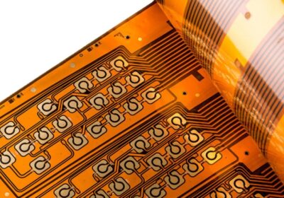
  

  Rigid-flex PCBs have revolutionized the electronics industry, offering a blend of the durability of rigid boards and the flexibility of flexible circuits. While these hybrid boards provide numerous advantages!such as reduced space and improved reliability!their manufacturing and application come with a range of challenges. In this article, we will explore the common challenges associated with rigid-flex PCB technology and provide practical solutions to address them.


  Table of Contents hide


  1 Challenges and Solutions for Rigid-Flex PCB Technology


  1.1 Introduction


  1.2 1. Design Complexity


  1.2.1 Challenge:


  1.2.2 Solution:


  1.3 2. Material Selection


  1.3.1 Challenge:


  1.3.2 Solution:


  1.4 3. Manufacturing Precision


  1.4.1 Challenge:


  1.4.2 Solution:


  1.5 4. Thermal Management


  1.5.1 Challenge:


  1.5.2 Solution:


  1.6 5. Testing and Inspection


  1.6.1 Challenge:


  1.6.2 Solution:


  1.7 6. Cost Factors


  1.7.1 Challenge:


  1.7.2 Solution:


  1.8 Solutions for Common Rigid-Flex PCB Challenges


  1.9 Conclusion


  1. Design Complexity


  Challenge:


  Rigid-flex PCBs require intricate designs to integrate both rigid and flexible parts effectively. The complexity lies in managing signal integrity, bending reliability, and the interaction between different layers. Moreover, ensuring that the flexible sections do not interfere with the functionality of the rigid parts is crucial.


  Solution:


  Collaborative Design Approach:Involve both the design and manufacturing teams early in the project to optimize the layout and mitigate risks.


  Design Automation Tools:Use advanced design software that provides tools for simulating signal flow and stress analysis in flex zones, ensuring better layout design for enhanced performance.


  Pre-Layout Simulation:Conduct pre-layout simulations to predict potential design issues, allowing for early adjustments.


  Rigid-Flex PCB technology


  Rigid-Flex PCB technology


  2. Material Selection


  Challenge:


  Selecting appropriate materials for rigid-flex PCBs is vital to maintaining durability and performance. Issues arise when materials selected for the rigid sections are incompatible with those used in the flexible areas, leading to issues like delamination and reduced flexibility.


  Solution:


  Balanced Material Selection:Choose materials that work well in both rigid and flexible sections, such as polyimide for the flex parts and FR-4 for rigid areas.


  Consider Environmental Conditions:Ensure materials are chosen based on the environmental conditions the PCB will face, such as temperature fluctuations, moisture, and vibration.


  Material Compatibility Testing:Perform thorough material compatibility testing to ensure that materials used in different layers adhere properly and maintain functionality.


  3. Manufacturing Precision


  Challenge:


  Manufacturing rigid-flex PCBs requires extreme precision to avoid misalignment between the rigid and flexible layers, which can lead to performance issues or complete circuit failure. Achieving the necessary precision during layer stacking and lamination is a significant challenge.


  Solution:


  Advanced Manufacturing Equipment:Invest in precision manufacturing equipment capable of handling the unique requirements of rigid-flex PCBs, including accurate layer stacking and alignment.


  Controlled Lamination Process:Ensure strict control over lamination conditions to prevent misalignment and warping, particularly in multi-layer designs.


  Quality Control Protocols:Implement comprehensive quality control protocols throughout the manufacturing process, including automated optical inspection (AOI) and X-ray inspection to ensure alignment.


  Rigid-Flex PCB technology


  Rigid-Flex PCB technology


  4. Thermal Management


  Challenge:


  Thermal management is critical in rigid-flex PCBs, especially in high-performance applications where heat dissipation is a concern. Poor thermal management can lead to overheating, reducing the lifespan of the board and components.


  Solution:


  Heat Dissipation Materials:Incorporate heat dissipation materials such as thermal vias or copper planes into the rigid sections to manage heat effectively.


  Design for Ventilation:Ensure adequate ventilation or thermal pathways in the PCB design to allow heat to dissipate naturally.


  Thermal Simulations:Use thermal simulation software during the design phase to predict hot spots and design effective cooling strategies.


  5. Testing and Inspection


  Challenge:


  Testing rigid-flex PCBs can be complex due to the multi-layered structure and the combination of rigid and flexible elements. Traditional testing methods may not detect issues specific to the flex areas or the connection between rigid and flex parts.


  Solution:


  Customized Testing Procedures:Develop customized testing procedures that address both the rigid and flexible sections. For example, use specialized testing methods like dynamic flex testing for the flexible areas.


  Automated Testing Tools:Use automated testing tools, including flying probe testers and boundary scan technologies, to ensure that even the smallest defects are detected.


  Regular Prototyping:Regularly create prototypes to test and identify issues early before moving on to full-scale production.


  Rigid-Flex PCB technologyRigid-Flex PCB technology


  6. Cost Factors


  Challenge:


  Rigid-flex PCBs are often more expensive to design and manufacture compared to traditional rigid PCBs or flexible circuits. The cost increases due to material selection, intricate design, and precision manufacturing.


  Solution:


  Design Optimization:Optimize the design to reduce material wastage and manufacturing complexity. For example, use a minimal number of layers or reduce the number of vias.


  Volume Production:Leverage economies of scale by producing in larger quantities, which can help reduce the per-unit cost.


  Supplier Collaboration:Work closely with suppliers like Gekunflex to source high-quality materials at competitive prices, ensuring cost efficiency without compromising quality.


  Solutions for Common Rigid-Flex PCB Challenges


  Addressing the challenges associated with rigid-flex PCBs requires a multi-faceted approach. By focusing on design optimization, careful material selection, precision in manufacturing, and effective thermal management, companies can overcome many of the difficulties these hybrid boards present. Additionally, thorough testing and cost management strategies can ensure the reliability and affordability of rigid-flex PCBs for various applications.


  At Gekunflex, we specialize in providing tailored solutions for all your rigid-flex PCB needs, ensuring that your products meet the highest standards of quality and performance. By collaborating with a trusted supplier, you can overcome the challenges associated with rigid-flex technology and achieve success in your projects.


  Conclusion


  Rigid-flex PCBs offer numerous advantages, but they also come with unique challenges. By employing the solutions discussed in this article!ranging from design improvements to cost management!manufacturers can enhance the reliability and performance of their rigid-flex PCB designs. Whether you¨re tackling complex designs or seeking to improve material compatibility, the key lies in optimizing every aspect of the process.


  For more information on rigid-flex PCBs and how we at Gekunflex can assist you in overcoming these challenges, contact our team of experts today.

In terms of working principle, the light emitting principle is unique

  In terms of working principle, the light emitting principle is unique: LED (Light Emitting Diode) is a light-emitting diode, and its core is a semiconductor chip. according to wholesale outdoor led display Industry veterans said that its development will still be in a good situation. https://ljx-led.com


  One end of the chip is the negative electrode, and the other end is connected to the positive electrode of the power supply, encapsulated with epoxy resin. When current passes through, electrons and holes are pushed towards the quantum well and recombine, emitting energy in the form of photons, thereby achieving luminescence.


  Moreover, the wavelength (i.e. color) of light is determined by the material forming the P-N junction, which allows LEDs to achieve a wide range of color variations.


  Accurate digital signal control: In LED displays, the brightness and color changes of each pixel are controlled by digital signals.


  Digital signal is a discrete form of signal that encodes various information in binary systems using a combination of “0” and “1”, including text, images, videos, etc.

Introduction

  This article provides a detailed overview of the key processes and considerations in electroplating, chemical plating, and hot air leveling for Flexible Printed Circuits (FPC). It highlights the importance of pre-treatment in electroplating for maintaining FPC performance, the challenges in controlling plating thickness, and issues related to post-plating stains. Additionally, the article discusses the application of chemical plating when FPC conductors cannot serve as electrodes and the quality concerns that may arise. Finally, it examines the use of hot air leveling on FPCs, focusing on adhesion strength and moisture resistance. Through this article, readers will gain a deeper understanding of the common challenges in FPC manufacturing and their solutions.After that, flexible PCB Not afraid of the future, dare to fight and fight, and won applause again and again in the market. https://gekunflex.com/


  FPC manufacturer


  FPC manufacturer


  FPC Plating Process


  1. Pre-treatment for FPC Electroplating


  After the flexible printed circuit (FPC) undergoes the coating process, the exposed copper conductors may be contaminated by adhesives or ink. Additionally, oxidation and discoloration caused by high-temperature processes can occur. To ensure good adhesion of the plating, these contaminants and oxidation layers must be removed, leaving the conductor surface clean.


  However, some contaminants are strongly bonded to the copper conductor, making it difficult to remove them with weak cleaning agents. Strong alkaline abrasives and brushing are typically used for this treatment. Since the adhesive used in the cover layer is often epoxy-based, which is not resistant to alkaline agents, this can weaken bonding strength. Although not immediately apparent, during the electroplating process, the plating solution may seep into the edges of the cover layer, and in severe cases, cause delamination of the cover layer.


  At the final soldering stage, solder might seep beneath the cover layer. Therefore, the pre-treatment cleaning process has a significant impact on the basic characteristics of the FPC, making it essential to pay close attention to the processing conditions.


  2. Thickness of FPC Electroplating


  The deposition rate of electroplating metal is directly related to the intensity of the electric field, which varies depending on the shape of the circuit and the position of the electrodes. Generally, the thinner the conductor line and the sharper the terminal end, the stronger the electric field, leading to a thicker plating in those areas.


  In FPC applications, there are often wide differences in the width of conductor lines within the same circuit, resulting in uneven plating thickness. To prevent this, auxiliary cathode patterns are added around the circuit to absorb uneven current distribution across the plating pattern, ensuring uniform plating thickness across all areas.


  Electrode structure is key here. A compromise approach can be adopted, where stricter standards apply to areas requiring high plating uniformity, such as molten solder (lead-tin) and gold plating for metal wire bonding, while areas requiring plating for general corrosion protection may have more relaxed thickness requirements.


  FPC manufacturer


  3. Contamination of FPC Electroplating


  Immediately after electroplating, the plated surface may appear fine, but stains, dirt, or discoloration can appear over time. Often, these issues are not detected during factory inspections but are discovered during customer acceptance tests. This happens when the plated surface is not adequately rinsed, leaving residual plating solution, which reacts chemically over time, especially on the flexible surface due to its softness and uneven texture.


  To prevent this, thorough rinsing and drying are essential. A high-temperature thermal aging test can verify whether rinsing was sufficient.


  FPC Chemical Plating


  When the conductor to be plated is isolated and cannot serve as an electrode, chemical plating must be used. Chemical plating solutions are highly reactive, and a common example is chemical gold plating. The chemical gold plating solution is an alkaline solution with a very high pH value.


  When using this process, it is easy for the plating solution to seep beneath the cover layer, especially if the lamination quality control is poor, leading to weak adhesion. Displacement reactions in chemical plating exacerbate this problem, making it difficult to achieve ideal plating conditions.


  FPC Hot Air Leveling (HASL)


  Hot air leveling was originally developed for rigid printed circuit boards (PCBs) to coat them with lead-tin. However, this technique has been applied to FPCs due to its simplicity. Hot air leveling involves immersing the board vertically into molten lead-tin and blowing off excess solder with hot air.


  These conditions are quite harsh for FPCs. Without special measures, FPCs cannot be immersed in molten solder. To address this, FPCs must be clamped between titanium-steel meshes before immersion. Additionally, the surface of the FPC must be cleaned and coated with flux beforehand.


  Due to the harsh nature of the hot air leveling process, solder may seep beneath the edges of the cover layer, especially if the bonding strength between the cover layer and the copper foil is weak. Since polyimide films are prone to moisture absorption, moisture can evaporate suddenly under the heat, causing blistering or even delamination of the cover layer. Therefore, drying and moisture control must be performed before FPC hot air leveling.


  FPC manufacturer


  FPC manufacturer


  Gekun is a leading manufacturer specializing in high-quality Flexible Printed Circuits (FPC). With years of experience in the industry, Gekun provides advanced FPC solutions tailored to various industries, including telecommunications, medical devices, automotive, and consumer electronics. Their manufacturing process emphasizes precision, reliability, and innovation, ensuring excellent performance and durability. For businesses looking for custom FPC designs or mass production, Gekun stands out as a trusted partner, offering both competitive pricing and cutting-edge technology.


  For more information on Gekun¨s FPC manufacturing capabilities, you can visit their official website or contact their team for specific inquiries.

Introduction

  This article provides a detailed overview of the key processes and considerations in electroplating, chemical plating, and hot air leveling for Flexible Printed Circuits (FPC). It highlights the importance of pre-treatment in electroplating for maintaining FPC performance, the challenges in controlling plating thickness, and issues related to post-plating stains. Additionally, the article discusses the application of chemical plating when FPC conductors cannot serve as electrodes and the quality concerns that may arise. Finally, it examines the use of hot air leveling on FPCs, focusing on adhesion strength and moisture resistance. Through this article, readers will gain a deeper understanding of the common challenges in FPC manufacturing and their solutions.precisely because flexible circuits The rapid development of, so also brought new opportunities to the industry. https://gekunflex.com/


  FPC manufacturer


  FPC manufacturer


  FPC Plating Process


  1. Pre-treatment for FPC Electroplating


  After the flexible printed circuit (FPC) undergoes the coating process, the exposed copper conductors may be contaminated by adhesives or ink. Additionally, oxidation and discoloration caused by high-temperature processes can occur. To ensure good adhesion of the plating, these contaminants and oxidation layers must be removed, leaving the conductor surface clean.


  However, some contaminants are strongly bonded to the copper conductor, making it difficult to remove them with weak cleaning agents. Strong alkaline abrasives and brushing are typically used for this treatment. Since the adhesive used in the cover layer is often epoxy-based, which is not resistant to alkaline agents, this can weaken bonding strength. Although not immediately apparent, during the electroplating process, the plating solution may seep into the edges of the cover layer, and in severe cases, cause delamination of the cover layer.


  At the final soldering stage, solder might seep beneath the cover layer. Therefore, the pre-treatment cleaning process has a significant impact on the basic characteristics of the FPC, making it essential to pay close attention to the processing conditions.


  2. Thickness of FPC Electroplating


  The deposition rate of electroplating metal is directly related to the intensity of the electric field, which varies depending on the shape of the circuit and the position of the electrodes. Generally, the thinner the conductor line and the sharper the terminal end, the stronger the electric field, leading to a thicker plating in those areas.


  In FPC applications, there are often wide differences in the width of conductor lines within the same circuit, resulting in uneven plating thickness. To prevent this, auxiliary cathode patterns are added around the circuit to absorb uneven current distribution across the plating pattern, ensuring uniform plating thickness across all areas.


  Electrode structure is key here. A compromise approach can be adopted, where stricter standards apply to areas requiring high plating uniformity, such as molten solder (lead-tin) and gold plating for metal wire bonding, while areas requiring plating for general corrosion protection may have more relaxed thickness requirements.


  FPC manufacturer


  3. Contamination of FPC Electroplating


  Immediately after electroplating, the plated surface may appear fine, but stains, dirt, or discoloration can appear over time. Often, these issues are not detected during factory inspections but are discovered during customer acceptance tests. This happens when the plated surface is not adequately rinsed, leaving residual plating solution, which reacts chemically over time, especially on the flexible surface due to its softness and uneven texture.


  To prevent this, thorough rinsing and drying are essential. A high-temperature thermal aging test can verify whether rinsing was sufficient.


  FPC Chemical Plating


  When the conductor to be plated is isolated and cannot serve as an electrode, chemical plating must be used. Chemical plating solutions are highly reactive, and a common example is chemical gold plating. The chemical gold plating solution is an alkaline solution with a very high pH value.


  When using this process, it is easy for the plating solution to seep beneath the cover layer, especially if the lamination quality control is poor, leading to weak adhesion. Displacement reactions in chemical plating exacerbate this problem, making it difficult to achieve ideal plating conditions.


  FPC Hot Air Leveling (HASL)


  Hot air leveling was originally developed for rigid printed circuit boards (PCBs) to coat them with lead-tin. However, this technique has been applied to FPCs due to its simplicity. Hot air leveling involves immersing the board vertically into molten lead-tin and blowing off excess solder with hot air.


  These conditions are quite harsh for FPCs. Without special measures, FPCs cannot be immersed in molten solder. To address this, FPCs must be clamped between titanium-steel meshes before immersion. Additionally, the surface of the FPC must be cleaned and coated with flux beforehand.


  Due to the harsh nature of the hot air leveling process, solder may seep beneath the edges of the cover layer, especially if the bonding strength between the cover layer and the copper foil is weak. Since polyimide films are prone to moisture absorption, moisture can evaporate suddenly under the heat, causing blistering or even delamination of the cover layer. Therefore, drying and moisture control must be performed before FPC hot air leveling.


  FPC manufacturer


  FPC manufacturer


  Gekun is a leading manufacturer specializing in high-quality Flexible Printed Circuits (FPC). With years of experience in the industry, Gekun provides advanced FPC solutions tailored to various industries, including telecommunications, medical devices, automotive, and consumer electronics. Their manufacturing process emphasizes precision, reliability, and innovation, ensuring excellent performance and durability. For businesses looking for custom FPC designs or mass production, Gekun stands out as a trusted partner, offering both competitive pricing and cutting-edge technology.


  For more information on Gekun¨s FPC manufacturing capabilities, you can visit their official website or contact their team for specific inquiries.

LED displays have a wide viewing angle of up to 160

  providing a good visual experience from any angle. This makes them highly advantageous in applications such as large venues and squares, where viewers can easily see the content on the screen from different positions. Actually, it’s not just this reason, commercial outdoor led display supplier Its own advantages are also obvious, and it is normal for the market to perform well. https://ljx-led.com


  In terms of technological innovation, 1: Flexible screen technology: Flexible LED displays can be installed on curved surfaces according to specific environments, and can fit various irregular surfaces such as cylinders, curved walls, etc., increasing decorative and visual effects, providing more possibilities for creative design and space utilization.


  Transparent screen technology: Transparent LED displays can achieve transparent visual effects, displaying images and information without affecting line of sight, providing a new display method for commercial displays

What is a Single-Sided Flexible PCB

  What is a Single-Sided Flexible PCB?This is due to flexible circuits Its value attribute is relatively large, and it is easy to become the backbone of the industry. https://gekunflex.com/


  A single-sided flexible PCB consists of one conductive layer, usually made of copper, and a flexible substrate. It is designed for simple, low-complexity circuits where electrical components are mounted only on one side. Single-sided flexible PCBs are highly flexible, lightweight, and cost-effective, making them ideal for applications that require a flexible connection or movement in confined spaces.


  Typical features of single-sided flexible PCBs include:


  One conductive layer


  Simple design and manufacturing process


  Reduced cost due to fewer materials


  Excellent flexibility, allowing bending and folding without compromising function


  Single-sided flexible PCBs are widely used in consumer electronics, medical devices, and automotive sensors, where space and weight are critical factors.


  What is a Double-Sided Flexible PCB?


  A double-sided flexible PCB has two conductive layers, one on each side of the flexible substrate. These layers are interconnected using vias (small plated holes), allowing more complex circuitry and higher component density than single-sided PCBs. The double-sided design offers enhanced functionality and flexibility for more advanced applications that require signal routing on both sides of the board.


  Key features of double-sided flexible PCBs include:


  Two conductive layers


  More complex designs for higher functionality


  Vias for inter-layer connectivity


  Higher component density, supporting more complex circuits


  Double-sided flexible PCBs are used in more sophisticated applications like industrial control systems, aerospace technology, and complex automotive electronics, where higher performance and reliability are required.


  Single-Sided Flexible PCB


  Key Differences Between Single-Sided and Double-Sided Flexible PCBs


  The primary differences between single-sided and double-sided flexible PCBs are their layer structure, functionality, and applications.


  Feature Single-Sided Flexible PCB Double-Sided Flexible PCB


  Number of Conductive Layers One layer Two layers (one on each side)


  Design Complexity Simple designs Supports more complex circuits


  Manufacturing Cost Lower cost due to fewer materials Higher cost due to additional layers


  Component Density Limited to one side Allows components on both sides


  Applications Consumer electronics, sensors, medical Aerospace, automotive, industrial


  Flexibility High flexibility Moderate flexibility


  Applications in Various Industries


  Single-sided flexible PCBs are commonly used in:


  Consumer Electronics: Remote controls, LED lighting systems, and mobile devices, where simplicity and low cost are essential.


  Automotive: Sensors and connectors that require lightweight and flexible designs.


  Medical Devices: Wearable health monitors and portable medical equipment, where small, flexible circuits are needed.


  Double-sided flexible PCBs find their place in more advanced applications, such as:


  Aerospace: Flight control systems and avionics that require high-reliability, complex circuitry in lightweight formats.


  Automotive: Engine control units, infotainment systems, and safety sensors.


  Industrial Equipment: Robotics and machinery that demand multi-layer circuits with high performance and durability.


  Choosing the Right Flexible PCB for Your Needs


  Selecting between a single-sided or double-sided flexible PCB depends on the specific needs of your project. If your application requires a simple, low-cost solution with minimal circuitry, a single-sided flexible PCB is often sufficient. However, for more complex designs requiring higher functionality and component density, a double-sided flexible PCB is the better option.


  Rigid-Flex Combination


  Gekun: Your Trusted Flexible PCB Manufacturer


  Whether you¨re looking for single-sided flexible PCBs for simple electronic applications or double-sided flexible PCBs for more advanced industrial or automotive projects, Gekun offers high-quality, reliable solutions. With our advanced manufacturing processes and commitment to innovation, we ensure that our products meet the highest standards for performance and durability. Partner with Gekun for your next project and experience the benefits of cutting-edge flexible PCB technology.


  Understanding the differences between single-sided and double-sided flexible PCBs is essential when choosing the right solution for your application. Both types offer unique advantages and are tailored to meet the needs of various industries. As technology advances, flexible PCBs will continue to play a crucial role in the development of innovative electronics, automotive systems, and aerospace technologies.


  For top-quality flexible PCBs, trust Gekun to deliver solutions that meet your specific needs, from design to production.

LED displays have a wide viewing angle of up to 160

  providing a good visual experience from any angle. This makes them highly advantageous in applications such as large venues and squares, where viewers can easily see the content on the screen from different positions. At first, commercial outdoor led display supplier It developed out of control and gradually opened up a sky of its own. https://ljx-led.com


  In terms of technological innovation, 1: Flexible screen technology: Flexible LED displays can be installed on curved surfaces according to specific environments, and can fit various irregular surfaces such as cylinders, curved walls, etc., increasing decorative and visual effects, providing more possibilities for creative design and space utilization.


  Transparent screen technology: Transparent LED displays can achieve transparent visual effects, displaying images and information without affecting line of sight, providing a new display method for commercial displays

Manufacturing Process of Multilayer Flexible Printed Circuit Boards (FPC)

  1. Introduction to Multilayer Flexible Printed Circuit Boards (FPC)Under people’s attention rigid flex pcb Finally grow into what people need, born for the market and come for the demand. https://gekunflex.com/


  Multilayer flexible printed circuit boards (FPCs) are at the forefront of modern electronic design, providing both flexibility and durability in high-performance environments. These circuits are made up of multiple layers of flexible material, usually polyimide, which allows them to bend and fold while maintaining their electrical performance. As devices become more compact and complex, especially in automotive, aerospace, and medical applications, the demand for multilayer FPCs continues to rise.


  In this article, we¨ll explore the manufacturing process of multilayer flexible printed circuit boards, highlighting their importance in key industries. We¨ll also emphasize the value of these boards in the European and American markets and how Gekun, a leader in FPC production, offers cutting-edge solutions.


  Multilayer Flexible Printed Circuit Boards


  Multilayer Flexible Printed Circuit Boards


  2. Key Steps in the Manufacturing Process


  Material Selection and Layer Construction


  The manufacturing of multilayer flexible printed circuit boards begins with selecting the appropriate materials. Polyimide is the standard base material due to its high-temperature resistance and flexibility. Copper layers are added to create conductive pathways, and the number of layers depends on the complexity of the design.


  Each layer is carefully constructed, starting with the outer flexible layer, followed by insulating and conductive layers in a sequence. The layers are aligned meticulously to ensure connectivity across all components.


  Imaging and Etching Process


  Once the layers are in place, the next step is to image and etch the copper to define the circuit paths. Photolithography techniques are used to project circuit designs onto the copper layer, which is then etched to remove unwanted areas. This step is critical to creating precise electrical pathways.


  Layer Alignment and Lamination


  After each layer is imaged and etched, the different layers are stacked and aligned using precision machinery. Any misalignment can cause failure in the final product, especially as the complexity of the multilayer flexible printed circuit board increases. The layers are then laminated using heat and pressure to form a single, unified structure.


  Drilling and Plating


  Once laminated, the board is drilled to create vias (small holes) that connect the different layers electrically. These vias are plated with copper to ensure proper conductivity between layers. The drilling and plating processes must be executed with high precision, as any defects can lead to failures in the finished product.


  Testing and Quality Control


  The final steps in the multilayer FPC manufacturing process involve rigorous testing to ensure electrical performance and durability. Automated optical inspection (AOI) systems are often used to detect defects, while electrical testing verifies the connectivity of all circuits. The quality control process ensures that the FPCs meet the high standards required for industries such as automotive, aerospace, and medical devices.


  3. Benefits of Multilayer FPCs in Different Industries


  Consumer Electronics and Automotive Applications


  The flexibility and lightweight nature of multilayer flexible printed circuit boards make them ideal for consumer electronics, such as smartphones and wearable devices. They allow manufacturers to create compact designs while maintaining excellent electrical performance. In the automotive industry, FPCs are used in advanced driver-assistance systems (ADAS) and infotainment systems, providing both durability and flexibility in harsh environments.


  Aerospace and Medical Device Markets


  In aerospace, where weight reduction and reliability are critical, multilayer FPCs offer a solution that meets stringent industry standards. Their ability to function under extreme conditions makes them valuable in aircraft avionics. Similarly, in the medical device sector, FPCs are widely used in diagnostic equipment and implantable devices, where their flexibility and high reliability are essential.


  Multilayer Flexible Printed Circuit Boards


  Multilayer Flexible Printed Circuit Boards


  4. Challenges in Manufacturing Multilayer FPCs


  Complex Design Requirements


  The design of multilayer flexible printed circuit boards presents significant challenges due to the need for precise alignment and electrical performance across multiple layers. Each layer must be carefully planned to ensure that the circuits are properly routed, and the design must accommodate the mechanical stresses that occur during bending and folding.


  Reliability and Durability Concerns


  In applications such as automotive and aerospace, FPCs are exposed to harsh conditions, including extreme temperatures and vibrations. Ensuring that the boards maintain their performance under these conditions requires advanced materials and manufacturing processes, which can increase production costs.


  5. The Role of Gekun in Multilayer FPC Manufacturing


  Gekun is a leader in the multilayer flexible printed circuit board market, providing high-quality solutions tailored to the needs of modern industries. With cutting-edge manufacturing facilities and a focus on innovation, Gekun offers FPCs that meet the most stringent industry standards. Their expertise in multilayer FPC manufacturing ensures that customers receive reliable, high-performance products suited for automotive, aerospace, and consumer electronics markets.


  Gekun¨s commitment to quality and precision makes them a trusted partner for businesses looking to innovate and stay ahead in the competitive market.


  Multilayer Flexible Printed Circuit Boards


  Multilayer Flexible Printed Circuit Boards


  6. Conclusion


  The multilayer flexible printed circuit board manufacturing process is a complex yet crucial aspect of modern electronics. These boards provide the flexibility and durability needed for advanced technologies in automotive, aerospace, and medical industries. By understanding the manufacturing steps, benefits, and challenges associated with multilayer FPCs, businesses can better appreciate their value in the global market.


  Gekun, as a trusted manufacturer, continues to lead the industry with innovative solutions that meet the demands of today¨s fast-paced technology landscape.